

COMPLIANCE INFORMATION STATEMENT
(DECLARATION OF CONFORMITY PROCEDURE)
Responsible Party: YAMAHA CORPORATION OF AMERICA
Address: 6600 Orangethorpe Avenue, Buena Park, Calif. 90620 U.S.A.
Telephone: 1-714-522-9011
FAX: 1-714-739-2680
Type of Equipment: AUDIO EXPANSION UNIT
Model Name: AX44
This device complies with Part 15 of the FCC Rules.
Operation is subject to the following conditions:
1) this device may not cause harmful interference, and
2) this device must accept any interference received including interference that may cause undesired operation.
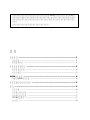
Contents
Introduction - - - - - - - - - - - - - - - - - - - - - - - - - - - - - - - - - - - 1
Packing List - - - - - - - - - - - - - - - - - - - - - - - - - - - - - - - - - 1
System Requirements - - - - - - - - - - - - - - - - - - - - - - - - - - - 1
Controls & Connections - - - - - - - - - - - - - - - - - - - - - - - - - - 2
Front Panel - - - - - - - - - - - - - - - - - - - - - - - - - - - - - - - - - - 2
Rear Panel - - - - - - - - - - - - - - - - - - - - - - - - - - - - - - - - - - 3
Installing the AX44 - - - - - - - - - - - - - - - - - - - - - - - - - - - - - - 4
Installing a Second AX44 - - - - - - - - - - - - - - - - - - - - - - - - - 4
Troubleshooting - - - - - - - - - - - - - - - - - - - - - - - - - - - - - - - - 5
Specifications - - - - - - - - - - - - - - - - - - - - - - - - - - - - - - - - - - 6
General - - - - - - - - - - - - - - - - - - - - - - - - - - - - - - - - - - - - 6
Analog Inputs - - - - - - - - - - - - - - - - - - - - - - - - - - - - - 7
Analog Outputs - - - - - - - - - - - - - - - - - - - - - - - - - - - - - - - 7
DC IN Connector - - - - - - - - - - - - - - - - - - - - - - - - - - - - - 7
Dimensions - - - - - - - - - - - - - - - - - - - - - - - - - - - - - - - - - 8
FCC INFORMATION (U.S.A.)
1. IMPORTANT NOTICE: DO NOT MODIFY THIS UNIT! This product, when installed as indicated in the instructions contained in this manual, meets FCC
requirements. Modifications not expressly approved by Yamaha may void your authority, granted by the FCC, to use the product.
2. IMPORTANT: When connecting this product to accessories and/or another product use only high quality shielded cables. Cable/s supplied with this product MUST
be used. Follow all installation instructions. Failure to follow instructions could void your FCC authorization to use this product in the USA.
3. NOTE: This product has been tested and found to comply with the requirements listed in FCC Regulations, Part 15 for Class “B” digital devices. Compliance with
these requirements provides a reasonable level of assurance that your use of this product in a residential environment will not result in harmful interference with
other electronic devices. This equipment generates/uses radio frequencies and, if not installed and used according to the instructions found in the users manual, may
cause interference harmful to the operation of other electronic devices. Compliance with FCC regulations does not guarantee that interference will not occur in all
installations. If this product is found to be the source of interference, which can be determined by turning the unit “OFF” and “ON”, please try to eliminate the
problem by using one of the following measures: Relocate either this product or the device that is being affected by the interference. Utilize power outlets that are on
different branch (circuit breaker or fuse) circuits or install AC line filter/s. In the case of radio or TV interference, relocate/reorient the antenna. If the antenna lead-in
is 300 ohm ribbon lead, change the lead-in to coaxial type cable. If these corrective measures do not produce satisfactory results, please contact the local retailer
authorized to distribute this type of product. If you can not locate the appropriate retailer, please contact Yamaha Corporation of America, Electronic Service
Division, 6600 Orangethorpe Ave, Buena Park, CA 90620
The above statements apply ONLY to those products distributed by Yamaha Corporation of America or its subsidiaries.

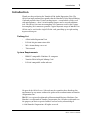
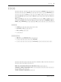
Introduction
1
AX44—Owner’s Manual
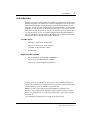
Introduction
Thank you for purchasing the Yamaha AX44 Audio Expansion Unit. The
AX44 is an input and output expander for the Yamaha DS2416 Digital Mixing
Card and provides four 1/4-inch analog inputs—two of which can be used
with microphones—four 1/4-inch analog outputs and a stereo headphone
jack. The 20-bit 128-times oversampling A/D converters and 18-bit 8-times
oversampling D/A converters provide a typical dynamic range of 100 dB. Two
AX44s can be used with a single DS2416 card, providing up to eight analog
inputs and outputs.
Packing List
• AX44 Audio Expansion Unit
• DS2416 20-pin connection cable
• M3 x 6 mm fixing screws x4
• This manual
System Requirements
• IBM PC compatible Windows 95 computer
• Yamaha DS2416 Digital Mixing Card
• DS2416 compatible audio software
No part of the AX44
Owner’s Manual
may be reproduced or distributed in
any form or by any means without the prior written authorization of Yamaha
Corporation, Inc.
IBM PC is a registered trademarks of International Business Machines, Inc.
Yamaha is a trademark of Yamaha Corporation, Inc. All other trademarks are
the property of their respective holders and are hereby acknowledged.
© 1998 Yamaha Corporation. All rights reserved.

2
Controls & Connections
AX44—Owner’s Manual
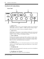
Controls & Connections
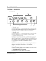
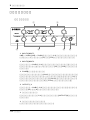
Front Panel
A
Inputs 1 & 2
Analog inputs 1 and 2 feature 1/4-inch unbalanced phone jacks with individ-
ual Line/Mic switches for –10 dBV or –50 dBV operation. Analog to digital
conversion features 20-bit 128-times oversampling techniques.
B
Inputs 3 & 4
Analog inputs 3 and 4 feature 1/4-inch unbalanced phone jacks with a nomi-
nal input level of –10 dBV. Use with line-level sources. Analog to digital con-
version uses 20-bit 128-times oversampling techniques.
C
Power Indicator
The Power indicator lights up when the AX44 is ready for use, that is, when
the computer is turned on and the AX44 is receiving power, and the connec-
tion to the DS2416 is functioning correctly. (It’s also used to identify AX44s
from the software, useful when two units are installed.)
D
Outputs 1–4
Outputs 1 through 4 feature 1/4-inch unbalanced phone jacks with a nominal
output level of –10 dBV. Digital to analog conversion features 18-bit 8-times
oversampling.
E
Headphone Jack
Outputs 3 and 4 can be monitored by connecting a pair of stereo headphones
to this 1/4-inch stereo jack.
F
Headphone Level Control
This control adjusts the volume level of the headphones.
INPUT 1 2 3 4
1234
OUTPUT
POWER
LINE MIC
–10dBV –50dBV –10dBV –50dBV
LINE MIC
AX44
4
21
3 5 6

Rear Panel
3
AX44—Owner’s Manual
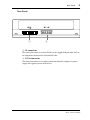
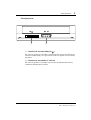
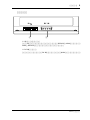
Rear Panel
A
IO connector
This connector connects to the DS2416 via the supplied 20-pin cable and car-
ries digital data between the AX44 and DS2416.
B
DC IN connector
This connector connects to a power connector from the computer’s power
supply and supplies power to the AX44.
IO DC IN
1 2

4
Installing the AX44
AX44—Owner’s Manual
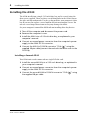
Installing the AX44
The AX44 installs into a single 5.25-inch drive bay, and is secured using the
four screws supplied. There are three sets of fixing holes in the AX44: two on
the sides and one underneath. Use the set that matches your computer’s drive
bay. If you need to replace a screw, look for M3 x 6 mm machine screws. Do
not use screws longer than 6 mm as they may damage the AX44.
See your computer’s manual for full details on installing drive bay devices.
1
Turn off the computer and disconnect the power cord.
2
Remove the computer’s cover.
3
Install the AX44 into a 5.25-inch drive bay, as explained in your
computer’s manual.
4
Connect an unused power connector from the computer’s power
supply to the AX44 DC IN connector.
5
Connect the AX44 to DS2416 connector “IO-A ( )” using the
supplied 20-pin cable (connect the end with the ferrite core to the
DS2416).
Installing a Second AX44
Two AX44 units can be connected to a single DS2416 card.
1
Install the second AX44 into a 5.25-inch drive bay, as explained in
your computer’s manual.
2
Connect an unused power connector from the computer’s power
supply to the AX44 DC IN connector.
3
Connect the second AX44 to DS2416 connector “IO-B ( )” using
the supplied 20-pin cable.
A
AB

Troubleshooting
5
AX44—Owner’s Manual
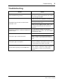
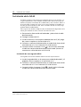
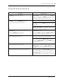
Troubleshooting
Trouble Advice
Lost the AX44 fixing screws?
Replace with M3 x 6 mm machine screws.
Do not use screws longer than 6 mm as they
may damage the AX44.
The AX44 does not work and the Power
indicator is off?
Make sure that the computer is turned on.
Make sure the power connector is properly
connected to the AX44.
Make sure the supplied 20-pin cable is con-
nected properly between the AX44 and
DS2416.
The Power indicator is on but the AX44 still
doesn’t work?
A single AX44 should be connected to
DS2416 connector “IO-A”; the second AX44
to connector “IO-B”.
The input signal sounds distorted?
Reduce the level of the input signal.
When connecting line-level equipment to
inputs 1 and 2, set the Mic/Line switches to
Line.
The input signal is too quiet?
Low-level signal sources such as micro-
phones should be connected to inputs 1 and
2 and the Mic/Line switch set to Mic.
Cannot hear anything in the headphones?
The headphone signal is derived from out-
puts 3 and 4, so you must assign signals to
these outputs in order to use the head-
phones.

6
Specifications
AX44—Owner’s Manual
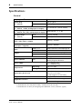
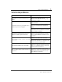
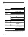
Specifications
General
1. Syncs to external wordclock. AX44 has no internal clock.
2. Bandwidth filter
±
0.1 dB (20 Hz–20 kHz), –60 dB (more than 24.1 kHz)
3. Bandwidth filter as above plus Weighting Filter (IEC60651 A curve, Tolerance: Type 0)
Sampling rate
1
30.08 to 50.88 kHz
Signal delay
(fs = 48 kHz)
A/D
610
µ
s typical
D/A
1,330
µ
s typical
Total harmonic distortion
2
(fs = 48 kHz, +6 dBV, analog input to output)
Less than 0.01% (20 Hz–20 kHz)
Frequency response
(fs = 48 kHz, Line, Mic, analog input to output)
20 Hz–20 kHz, –3, +1 dB
Dynamic range
3
(fs = 48 kHz)
D/A
Typically 106 dB
A/D + D/A
Typically 100 dB
Equivalent input noise
3
(Gain = Mic, input + output)
Typically –120 dBV
Residual output noise
3
(D/A input = digital 0)
Typically –100 dBV
Input
INPUT 1–4 20-bit 128-times oversampling A/D
INPUT 1, 2 MIC/LINE switch
Output
OUTPUT 1–4 18-bit 8-times oversampling D/A
Phones Source: outputs 3 and 4
Phones level control
Rotary pot
Power indicator
LED
Power on/off
Identity flag from DS2416
Power supply
+5 V (180 mA max)
+12 V (200 mA max)
Temperature
Operating
+10˚C to +40˚C
Storage
–20˚C to +55˚C
Dimensions (W x D x H)
148 x 183 x 42.6 mm
(5.8 x 7.2 x 1.7 inch)
For half-height 5.25" drive bay
Weight
1 kg (2.2 lbs)
Supplied accessories
20-pin DS2416 connecting cable x1
M3 x 6 mm fixing screws x4

Analog Outputs
7
AX44—Owner’s Manual
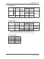
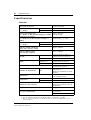
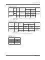
Analog Inputs
Analog Outputs
DC IN Connector
1. Input channels 1–4 feature linear 20-bit 128-times oversampling A/D converters.
2. Where dBV represents a specific voltage, 0 dBV is referenced to 1 V rms.
1. Output channels 1–4 feature linear 18-bit 8-times oversampling D/A converters.
2. Where dBV represents a specific voltage, 0 dBV is referenced to 1 V rms.
3. The Phones stereo phone jack is wired: tip = left, ring = right, sleeve = ground.
Connection Pad
Actual load
impedance
For use
with
nominal
Input level
Connector
Nominal
Max. before
clip
INPUT 1, 2
1
MIC
10k
Ω
50–600
Ω
mics &
600
Ω
lines
–50 dBV
2
(3.16 mV)
–34 dBV
(19.95 mV)
Phone jack
(unbalanced)
LINE
–10 dBV
(316 mV)
+6 dBV
(1.995 V)
INPUT 3, 4
10k Ω 600 Ω lines
–10 dBV
(316 mV)
+6 dBV
(1.995 V)
Connection
Actual
source
impedance
For use with
nominal
Output level
Connector
Nominal
Max. before
clip
OUTPUT 1–4
1
600 Ω 10k Ω lines
–10 dBV
2
(316 mV)
+6 dBV
(1.995 V)
Phone jack
(unbalanced)
Phones
3
22 Ω
8 Ω phones 1 mW 14 mW
Stereo phone
jack
40 Ω phones 1 mW 23 mW
Pin Signal
1 +12 V
2 GND
3 GND
4 +5 V

8 Specifications
AX44—Owner’s Manual
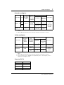
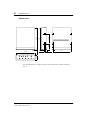
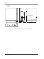
Dimensions
Specifications subject to change without notice.
M3 fixing holes (12 off)
139.711.8 10.65
D: 183
79.252.2
H: 42.6
W:148
5
188

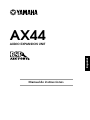
AX44
BOÎTIER D’EXTENSION
Mode d’emploi
Français

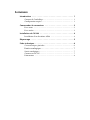
Sommaire
Introduction - - - - - - - - - - - - - - - - - - - - - - - - - - - - - - - - - - - 1
Contenu de l’emballage - - - - - - - - - - - - - - - - - - - - - - - - - - 1
Configuration requise - - - - - - - - - - - - - - - - - - - - - - - - - - - 1
Commandes & connexions - - - - - - - - - - - - - - - - - - - - - - - - 2
Face avant - - - - - - - - - - - - - - - - - - - - - - - - - - - - - - - - - - 2
Face arrière - - - - - - - - - - - - - - - - - - - - - - - - - - - - - - - - - - 3
Installation de l’AX44 - - - - - - - - - - - - - - - - - - - - - - - - - - - - 4
Installation d’un deuxième AX44 - - - - - - - - - - - - - - - - - - - 4
Dépannage - - - - - - - - - - - - - - - - - - - - - - - - - - - - - - - - - - - - 5
Fiche technique - - - - - - - - - - - - - - - - - - - - - - - - - - - - - - - - - 6
Caractéristiques générales - - - - - - - - - - - - - - - - - - - - - - - - 6
Entrées analogiques - - - - - - - - - - - - - - - - - - - - - - - - - 7
Sorties analogiques - - - - - - - - - - - - - - - - - - - - - - - - - - - - - 7
Connecteur DC IN - - - - - - - - - - - - - - - - - - - - - - - - - - - - - 7
Dimensions - - - - - - - - - - - - - - - - - - - - - - - - - - - - - - - - - 8

Introduction
1
AX44—Mode d’emploi
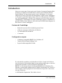
Introduction
Nous vous remercions d’avoir opté pour le boîtier d’extension Yamaha AX44.
L’AX44 est un boîtier d’extension entrées/sorties pour la Yamaha DS2416
Digital Mixing Card qui propose quatre sorties analogiques 1/4 de pouce
(dont deux peuvent servir pour des microphones), quatre sorties analogiques
1/4 de pouce et une borne pour casque stéréo. Les convertisseurs A/N 20 bits
avec suréchantillonnage à 128 fois et les convertisseurs N/A 18 bits avec suré-
chantillonnage à 8 fois offrent une plage dynamique typique de 100 dB. Il est
possible d’utiliser deux AX44 avec une seule carte DS2416 afin de disposer de
huit entrées et sorties analogiques.
Contenu de l’emballage
• Boîtier d’extension AX44 (Audio Expansion Unit)
• Câble de connexion à 20 broches du DS2416
• Vis de fixation M3 x 6 mm x4
•Ce manuel
Configuration requise
• Ordinateur compatible IBM PC avec Windows 95
• Yamaha DS2416 Digital Mixing Card
• Logiciel audio compatible DS2416
Il est interdit de reproduire ou de distribuer le
Mode d’emploi
de l’AX44 en
tout ou en partie, sous quelque forme ou par quelque moyen que ce soit sans
autorisation préalable et écrite de Yamaha Corporation, Inc.
IBM PC est une marque déposée de International Business Machines, Inc.
Yamaha est une marque commerciale de Yamaha Corporation, Inc. Toutes les
autres marques sont la propriété de leurs détenteurs respectifs et sont recon-
nues par la présente.
© 1998 Yamaha Corporation. Tous droits réservés.

2
Commandes & connexions
AX44—Mode d’emploi
Commandes & connexions
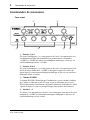
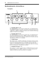
Face avant
A
Entrées 1 & 2
Les entrées analogiques 1 et 2 sont pourvues de jacks 1/4 asymétriques avec
un commutateur Line/Mic individuel leur permettant de sélectionner
–10 dBV ou –50 dBV. La conversion analogique/numérique se fait avec un
suréchantillonnage 20 bits à 128 fois.
B
Entrées 3 & 4
Les entrées analogiques 3 et 4 sont pourvues de jacks 1/4 asymétriques d’un
niveau d’entrée nominal de –10 dBV et sont prévues pour des sources de
niveau ligne. La conversion analogique/numérique se fait avec un suréchan-
tillonnage 20 bits à 128 fois.
C
Témoin POWER
Le témoin POWER s’allume lorsque l’ordinateur est sous tension et indique
que l’AX44 est alimenté et prêt à l’usage et que la connexion avec la carte
DS2416 fonctionne correctement. (Il permet également d’identifier les AX44
à partir du logiciel, ce qui est pratique lorsque vous utilisez deux boîtiers).
D
Sorties 1~4
Les sorties 1 à 4 sont pourvues de jacks 1/4 asymétriques d’un niveau de sortie
nominal de –10 dBV. La conversion numérique/analogique se fait avec un
suréchantillonnage 18 bits à 8 fois.
INPUT 1 2 3 4
1234
OUTPUT
POWER
LINE MIC
–10dBV –50dBV –10dBV –50dBV
LINE MIC
AX44
4
21
3 5 6

Face arrière
3
AX44—Mode d’emploi
E
Prise pour casque
Vous pouvez écouter les sorties 3 et 4 en branchant un casque à cette prise sté-
réo.
F
Commande de volume du casque
Cette commande permet de régler le volume du casque.
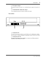
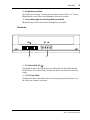
Face arrière
A
Connecteur IO
Ce connecteur permet de relier la carte DS2416 avec le câble fourni à 20 bro-
ches et permet le transfert de données numériques entre l’AX44 et le DS2416.
B
Connecteur DC IN
Ce connecteur permet de relier l’AX44 à un connecteur d’alimentation de
l’ordinateur afin d’alimenter l’AX44.
IO DC IN
1 2

4
Installation de l’AX44
AX44—Mode d’emploi
Installation de l’AX44
L’AX44 s’insère dans une baie simple de 5,25 pouces. Fixez-la avec les quatre
vis fournies. Il y a trois séries d’orifices de fixation dans l’AX44: deux sur les
côtés et un en-dessous. Servez-vous des orifices qui correspondent à ceux de
la baie de votre ordinateur. Si vous devez remplacer une vis, demandez une vis
pour machine M3 x 6 mm. N’utilisez pas de vis plus longues que 6 mm car
elles risqueraient d’endommager l’AX44.
Veuillez consulter le manuel de votre ordinateur pour en savoir davantage sur
l’installation d’appareils dans les baies.
1
Coupez l’ordinateur et débranchez le cordon d’alimentation.
2
Enlevez le cache de l’ordinateur.
3
Installez l’AX44 dans une baie de 5,25 pouces en suivant les expli-
cations données dans le manuel de votre ordinateur.
4
Branchez un connecteur d’alimentation inutilisé de l’ordinateur au
connecteur DC IN de l’AX44.
5
Branchez l’AX44 au connecteur “IO-A ( )” du DS2416 avec le
câble à 20 broches fourni (Connectez le côté en ferrite à la
DS2416).
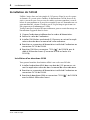
Installation d’un deuxième AX44
Vous pouvez brancher deux boîtiers AX44 à une seule carte DS2416.
1
Installez le deuxième AX44 dans une baie de 5,25 pouces en sui-
vant les explications données dans le manuel de votre ordinateur.
2
Branchez un connecteur d’alimentation inutilisé de l’ordinateur au
connecteur DC IN de l’AX44.
3
Branchez le deuxième AX44 au connecteur “IO-B ( )” du DS2416
avec le câble à 20 broches fourni.
A
AB

Dépannage
5
AX44—Mode d’emploi
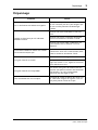
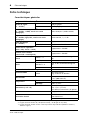
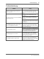
Dépannage
Problème Conseil
Les vis de fixations de l’AX44 sont égarées.
Remplacez-les par des vis machine M3 x
6 mm. N’utilisez pas de vis plus longues que
6 mm car elles pourraient endommager
l’AX44.
L’AX44 ne fonctionne pas et l’indicateur
POWER est éteint.
Assurez-vous que l’ordinateur est sous ten-
sion.
Assurez-vous que le connecteur d’alimenta-
tion est correctement raccordé à l’AX44.
Assurez-vous que le câble à 20 broches est
correctement relié à l’AX44 et à la carte
DS2416.
L’indicateur POWER est allumé mais l’AX44
ne fonctionne toujours pas.
Un boîtier AX44 unique doit être branché au
connecteur “IO-A” de la carte DS2416; bran-
chez le second au connecteur “IO-B”.
Le signal d’entrée est saturé?
Réduisez le niveau du signal d’entrée.
Lorsque vous branchez du matériel de niveau
ligne aux entrées 1 et 2, réglez les commuta-
teurs Mic/Line sur Line.
Le signal d’entrée est-il trop faible?
Les sources de signaux de faible niveau tels
que des microphones doivent être branchées
aux entrées 1 et 2 et le commutateur
Mic/Line doit être réglé sur Mic.
Vous n’entendez rien via le casque?
Le signal du casque est dérivé des sorties 3 et
4; il faut donc assigner les signaux à ces sor-
ties pour pouvoir utiliser le casque.

6
Fiche technique
AX44—Mode d’emploi
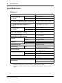
Fiche technique
Caractéristiques générales
1. Synchronisation sur horloge externe. L’AX44 n’a pas d’horloge interne.
2. Largeur de bande du filtre
±
0,1 dB (20 Hz–20 kHz), –60 dB (plus de 24,1 kHz)
3. Largeur de bande du filtre comme ci-dessus plus Filtre de pondération (IEC60651 courbe A,
Tolérance: Type 0)
Fréquence d’échantillonnage
1
30,08 à 50,88 kHz
Retard de signal
(fs = 48 kHz)
A/N
610
µ
s typique
N/A
1,330
µ
s typique
Distorsion harmonique totale
2
(fs = 48 kHz, +6 dBV, entrée vers sortie
analogique)
Moins de 0,01% (20 Hz–20 kHz)
Réponse en fréquence
(fs = 48 kHz, Ligne, Mic, entrée vers sortie
analogique)
20 Hz–20 kHz, –3, +1 dB
Plage dynamique
3
(fs = 48 kHz)
D/A
Typiquement 106 dB
A/D + D/A
Typiquement 100 dB
Bruit d’entrée équivalent
3
(Gain = Mic, entrée + sortie)
Typiquement –120 dBV
Bruit de sortie résiduel
3
(entrée N/A = numérique 0)
Typiquement –100 dBV
Entrée
INPUT 1~4
A/N 20 bits suréchantillonnage à 128
fois
INPUT 1, 2 Commutateur MIC/LINE
Sortie
OUTPUT 1~4
N/A 18 bits suréchantillonnage à 8
fois
Casque Source: sorties 3 et 4
Commande de volume du casque
Potentiomètre rotatif
Témoin POWER
Diode
Sous/hors tension
Flag d’identité du DS2416
Alimentation
+5 V (180 mA max)
+12 V (200 mA max)
Température
Fonctionnement
+10˚C à +40˚C
Stockage
–20˚C à +55˚C
Dimensions (L x P x H)
148 x 183 x 42,6 mm
(5,8 x 7,2 x 1,7 inch)
Pour baie mi-hauteur de 5,25 pouces
Poids
1 kg (2,2 lbs)
Accessoires fournis
Câble de connexion à 20 broches
pour DS2416 x1
Vis de fixation M3 x 6 mm x4

Sorties analogiques
7
AX44—Mode d’emploi
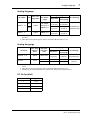
Entrées analogiques
Sorties analogiques
Connecteur DC IN
1. Les canaux d’entrée 1~4 disposent de convertisseurs A/N linéaires 20 bits avec suréchan-
tillonnage à 128 fois.
2. Lorsque dBV représente une tension spécifique, 0 dBV est référencé à 1 V rms.
1. Les canaux de sortie 1~4 disposent de convertisseurs N/A linéaires 18 bits avec suréchan-
tillonnage à 8 fois.
2. Lorsque dBV représente une tension spécifique, 0 dBV est référencé à 1 V rms.
3. Voici le câblage du jack du casque: pointe = gauche, anneau = droite, gaine = masse.
Connexion Att.
Impédance
de charge
réelle
Niveau
nominal
Niveau d’entrée
Connecteur
Nominal
Max. avant
saturation
INPUT 1, 2
1
MIC
10k
Ω
50–600
Ω
micro &
600
Ω
ligne
–50 dBV
2
(3,16 mV)
–34 dBV
(19,95 mV)
Jack
(asymétrique)
LINE
–10 dBV
(316 mV)
+6 dBV
(1,995 V)
INPUT 3, 4
10k
Ω
600
Ω
ligne
–10 dBV
(316 mV)
+6 dBV
(1,995 V)
Connexion
Impédance
de source
réelle
Niveau
nominal
Niveau de sortie
Connecteur
Nominal
Max. avant
saturation
OUTPUT 1~4
1
600 Ω 10k Ω ligne
–10 dBV
2
(316 mV)
+6 dBV
(1,995 V)
Jack
(asymétrique)
Casque
3
22 Ω
8 Ω casque 1 mW 14 mW
Prise pour cas-
que stéréo
40 Ω casque 1 mW 23 mW
Broche Signal
1 +12 V
2 Masse
3 Masse
4 +5 V

8 Fiche technique
AX44—Mode d’emploi
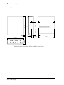
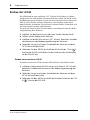
Dimensions
Caractéristiques susceptibles d’être modifiées sans préavis.
Orifices M3 (renfoncés 12)
139.711.8 10.65
P: 183
79.252.2
H: 42.6
L: 148
5
188
Stránka se načítá ...
Stránka se načítá ...
Stránka se načítá ...
Stránka se načítá ...
Stránka se načítá ...
Stránka se načítá ...
Stránka se načítá ...
Stránka se načítá ...
Stránka se načítá ...
Stránka se načítá ...
Stránka se načítá ...
Stránka se načítá ...
Stránka se načítá ...
Stránka se načítá ...
Stránka se načítá ...
Stránka se načítá ...
Stránka se načítá ...
Stránka se načítá ...
Stránka se načítá ...
Stránka se načítá ...
Stránka se načítá ...
Stránka se načítá ...
Stránka se načítá ...
Stránka se načítá ...
Stránka se načítá ...
Stránka se načítá ...
Stránka se načítá ...
Stránka se načítá ...
Stránka se načítá ...
Stránka se načítá ...
Stránka se načítá ...
-
 1
1
-
 2
2
-
 3
3
-
 4
4
-
 5
5
-
 6
6
-
 7
7
-
 8
8
-
 9
9
-
 10
10
-
 11
11
-
 12
12
-
 13
13
-
 14
14
-
 15
15
-
 16
16
-
 17
17
-
 18
18
-
 19
19
-
 20
20
-
 21
21
-
 22
22
-
 23
23
-
 24
24
-
 25
25
-
 26
26
-
 27
27
-
 28
28
-
 29
29
-
 30
30
-
 31
31
-
 32
32
-
 33
33
-
 34
34
-
 35
35
-
 36
36
-
 37
37
-
 38
38
-
 39
39
-
 40
40
-
 41
41
-
 42
42
-
 43
43
-
 44
44
-
 45
45
-
 46
46
-
 47
47
-
 48
48
-
 49
49
-
 50
50
-
 51
51


v jiných jazycích
- polski: Yamaha AX44 Instrukcja obsługi
- español: Yamaha AX44 El manual del propietario
- italiano: Yamaha AX44 Manuale del proprietario
- Deutsch: Yamaha AX44 Bedienungsanleitung
- svenska: Yamaha AX44 Bruksanvisning
- português: Yamaha AX44 Manual do proprietário
- français: Yamaha AX44 Le manuel du propriétaire
- 日本語: Yamaha AX44 取扱説明書
- Türkçe: Yamaha AX44 El kitabı
- English: Yamaha AX44 Owner's manual
- dansk: Yamaha AX44 Brugervejledning
- русский: Yamaha AX44 Инструкция по применению
- Nederlands: Yamaha AX44 de handleiding
- română: Yamaha AX44 Manualul proprietarului
Související papíry
-
Yamaha DS2416 Návod k obsluze
-
-
-
-
-
-
-
-
-