Yamaha PW3000MA Uživatelský manuál
- Kategorie
- Napájecí zdroje
- Typ
- Uživatelský manuál

POWER SUPPLY
Owner’s Manual
Mode d’emploi
Bedienungsanleitung
M

2
FCC INFORMATION (U.S.A.)
1. IMPORTANT NOTICE: DO NOT MODIFY THIS UNIT! This product, when installed as indicated in the instructions contained in this manual, meets FCC
requirements. Modifications not expressly approved by Yamaha may void your authority, granted by the FCC, to use the product.
2. IMPORTANT: When connecting this product to accessories and/or another product use only high quality shielded cables. Cable/s supplied with this product MUST
be used. Follow all installation instructions. Failure to follow instructions could void your FCC authorization to use this product in the USA.
3. NOTE: This product has been tested and found to comply with the requirements listed in FCC Regulations, Part 15 for Class “B” digital devices. Compliance with
these requirements provides a reasonable level of assurance that your use of this product in a residential environment will not result in harmful interference with
other electronic devices. This equipment generates/uses radio frequencies and, if not installed and used according to the instructions found in the users manual, may
cause interference harmful to the operation of other electronic devices. Compliance with FCC regulations does not guarantee that interference will not occur in all
installations. If this product is found to be the source of interference, which can be determined by turning the unit “OFF” and “ON”, please try to eliminate the
problem by using one of the following measures: Relocate either this product or the device that is being affected by the interference. Utilize power outlets that are on
different branch (circuit breaker or fuse) circuits or install AC line filter/s. In the case of radio or TV interference, relocate/reorient the antenna. If the antenna lead-in
is 300 ohm ribbon lead, change the lead-in to coaxial type cable. If these corrective measures do not produce satisfactory results, please contact the local retailer
authorized to distribute this type of product. If you can not locate the appropriate retailer, please contact Yamaha Corporation of America, Electronic Service
Division, 6600 Orangethorpe Ave, Buena Park, CA 90620
The above statements apply ONLY to those products distributed by Yamaha Corporation of America or its subsidiaries.
WARNING: THIS APPARATUS MUST BE EARTHED
IMPORTANT
THE WIRES IN THIS MAINS LEAD ARE COLOURED IN
ACCORDANCE WITH THE FOLLOWING CODE:
GREEN-AND-YELLOW : EARTH
BLUE : NEUTRAL
BROWN : LIVE
As the colours of the wires in the mains lead of this apparatus may
not correspond with the coloured markings identifying the terminals in
your plug, proceed as follows:
The wire which is coloured GREEN and YELLOW must be
connected to the terminal in the plug which is marked by the letter E
or by the safety earth symbol or coloured GREEN and YELLOW.
The wire which is coloured BLUE must be connected to the terminal
which is marked with the letter N or coloured BLACK.
The wire which is coloured BROWN must be connected to the
terminal which is marked with the letter L or coloured RED.
* This applies only to products distributed by YAMAHA KEMBLE
MUSIC (U.K.) LTD.

3
■
Precautions
• Connect the power supply power cord only to an AC
outlet of the type stated in this
Owner’s Manual
or as
marked on the power supply unit. Failure to do so is a
fire and electrical shock hazard.
• Do not locate the power supply unit in a place subject
to excessive heat or in direct sunlight. This could be a
fire hazard.
• Do not place the power supply unit in a place subject
to excessive humidity or dust. This could be a fire and
electrical shock hazard.
• Do not plug several devices into the same AC outlet.
This may overload the AC outlet, and could be a fire
and electrical shock hazard. It may also affect the per-
formance of some equipment.
• Do not place heavy objects on the power cord. A dam-
aged power cord is a potential fire and electrical shock
hazard.
• If the power cord is damaged (i.e., cut or a bare wire is
exposed), ask your dealer for a replacement. Using the
power supply unit in this condition is a fire and shock
hazard.
• Hold the power cord plug when disconnecting from
an AC outlet. Never pull the cord. Damaging the
power cord in this way is a potential fire and electrical
shock hazard.
• Do not place small metal objects on top of the power
supply unit. Metal objects inside the power supply
unit are a fire and electrical shock hazard.
• Do not block the power supply unit ventilation slots.
The power supply unit has ventilation slots at the
front to prevent the internal temperature from rising.
Blocked ventilation slots are a fire hazard.
• Leave a reasonable amount of free-air space around
the power supply unit.
• If the power supply unit is to be rack mounted, leave
at least 10 cm free above the top panel and behind the
rear panel. When the power supply unit is in use,
remove the rear of the rack, or open its ventilation
slots to prevent overheating, which could be a fire
hazard.
• Do not try to modify the power supply unit. This
could be a fire and electrical shock hazard.
• The power supply unit operating temperature is
between 5˚C and 35˚C (41˚F and 95˚F).
• Turn off all audio devices and speakers when connect-
ing to the power supply unit. Refer to the owner’s
manual for each device. Use the correct cables and
connect as specified.
• If you notice any abnormality—such as smoke, odor,
or noise—turn off the power supply unit immediately.
Remove the power cord from the AC outlet. Confirm
that the abnormality is no longer present. Consult
your dealer for repair. Using the power supply unit in
this condition is a fire and shock hazard.
• If a foreign object or water gets inside the power sup-
ply unit, turn it off immediately. Remove the power
cord from the AC outlet. Consult your dealer for
repair. Using the power supply unit in this condition
is a fire and electrical shock hazard.
• If you plan not to use the power supply unit for a long
period of time, remove the power cord from the AC
outlet. Leaving the power supply unit connected is a
fire hazard.
• Do not use benzene, thinner, cleaning detergent, or a
chemical cloth to clean the power supply unit. Use
only a soft, dry cloth.
• The power supply unit uses high-frequency digital cir-
cuits that may cause interference on radios and televi-
sions placed close to it. If interference does occur,
relocate the affected equipment.
For European Model
Purchaser/User information specified in EN55103-1 and
EN55103-2.
Inrush Current: 44A
Conformed Environment: E1, E2, E3 and E4.

4
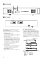
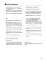
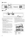
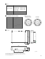
■
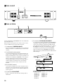
Front panel
■
Rear panel
The PW3000MA power supply should be installed in a
well ventilated location.
In particular, the front and rear panels must not be
blocked, since the ventilation path passes through them.
A
POWER ON/OFF
switch
After connections to the mixer have been completed,
turn this switch on to supply power to the mixer.
B
Operation monitor
These LEDs indicate the status of the four types of
power that are being supplied to the mixer. Normally
(i.e., when no malfunction has occurred), the green
LEDs (NORMAL) will light. If a malfunction occurs,
the LED for that section of the power supply will go
dark. Turn the power off and wait for a time before
turning the power on again. If the same LED(s) are
dark, contact a Yamaha service center.
C
GND terminals
This is the grounding screw terminal. If hum or noise
occurs, ground (earth) the unit via this jack, or try
connecting it to the chassis of the other device.
D
DC OUTPUT
connector
Connect this connector to the mixer to supply power
to it.
E
DC PARALLEL INPUT
connector
This connector allows two PW3000MA units to be
connected in parallel. As shown in the following dia-
gram, use the included parallel connection cable to
make connections. In this case, the two PW3000MA
units will each supply 50% of the power in normal
operation. Even in the unlikely event that one of the
PW3000MA units failed, the other PW3000MA will
supply 100% of the power, ensuring an uninterrupted
power supply.
The PW3000MA power supply can be used with the
following mixers.
M2500-56C M3000A-56C
M2500-48C M3000A-40C
M2500-40C M3000A-32
M2500-32 M3000A-24
M2500-24
POWER
OPERATION MONITOR
POWER SUPPLY
ON/ OFF
NORMAL
+48V +12V +15V –15V
1 2
DC OUTPUT
CONNECT
DISCONNECT
PIN 2 +15V 5.0A
PIN 5
–15V 5.0A
PIN 6 +12V 5.0A
PIN 9 +48V 0.2A
DC PARALLEL INPUT
CONNECT
DISCONNECT
5 4
3
DC OUTPUT
CONNECT
DISCONNECT
PIN 2 +15V 5.0A
PIN 5
–15V 5.0A
PIN 6 +12V 5.0A
PIN 9 +48V 0.2A
DC PARALLEL INPUT
CONNECT
DISCONNECT
DC OUTPUT
CONNECT
DISCONNECT
PIN 2 +15V 5.0A
PIN 5
–15V 5.0A
PIN 6 +12V 5.0A
PIN 9 +48V 0.2A
DC PARALLEL INPUT
CONNECT
DISCONNECT
PW3000MA
PW3000MA
DC POWER
INPUT
DC OUTPUT
DC OUTPUT
DC PARALLEL
INPUT

5
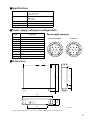
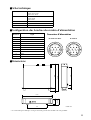
■
Specifications
■
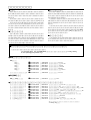
Power supply cable pin configuration
■
Dimensions
• Specifications and appearance are subject to change without notice for improvement.
Power Requirements USA and Canada: 120 V, 60 Hz
Europe: 230 V, 50 Hz
Others: 240 V, 50 Hz
Power Consumptions USA and Canada: 500 W, 600 VA
Europe: 500 W
Others: 500 W
Dimension (W x H x D) 480 mm x 103.5 mm x 455 mm
Weight 15 kg
Accessories Parallel connection cable (1 m)
Pin No. Signal name
Power supply connector
1 Power supply remote
2 +15 V
3
±
15 V GND
4 +48 V GND
5 –15 V
6 +12 V
7 +12 V GND/ power supply remote
8 Power supply remote
9 +48 V
10 FRAME GND
DC OUTPUT
DC PARALLEL INPUT
123
8910
5467
321
1098
6754
D:455
W:480
88
H:103.5
56.8 292
308
49.4 405.6
Units: mm

POWER SUPPLY
Mode d’emploi
Français

9
■
Précautions
• Branchez le cordon d’alimentation du bloc d’alimenta-
tion à une prise du type décrit dans ce
Mode d’emploi
ou
sur le bloc d’alimentation. Le non-respect de ces consi-
gnes peut provoquer un incendie ou une électrocution
• Ne placez pas le bloc d’alimentation à un endroit soumis
à une chaleur excessive ou en plein soleil. Cela peut pro-
voquer un incendie.
• Ne placez pas le bloc d’alimentation dans un endroit
excessivement humide ou poussiéreux. Cela peut provo-
quer un incendie ou une électrocution.
• Evitez de brancher plusieurs appareils sur la même prise.
Celle-ci risque d’être surchargée ce qui peut provoquer
un incendie ou une électrocution. Cela peut en outre
altérer les performances d’autres appareils.
• Ne placez pas d’objets lourds sur le cordon d’alimenta-
tion. Un cordon endommagé peut provoquer un incen-
die ou une électrocution
.
• Si le cordon d’alimentation est endommagé (entaillé
ou lorsqu’un fil est mis à nu), demandez un nouveau
cordon à votre revendeur. L’utilisation du bloc d’ali-
mentation dans cet état risque de provoquer un incen-
die ou une électrocution
.
• Lorsque vous débranchez le cordon d’alimentation, tirez
toujours sur la prise et pas sur le cordon. Un cordon
endommagé peut provoquer un incendie ou une électro-
cution
.
• Evitez de placer de petits objets sur le bloc d’alimenta-
tion. Si de petits objets métalliques s’introduisent dans le
boîtier, il y a risque d’incendie ou d’électrocution
.
• Ne bloquez pas les orifices d’aération du bloc d’ali-
mentation. Il est pourvu de fentes d’aération à l’avant
afin d’éviter que la température intérieure ne monte
excessivement. Le blocage de ces fentes peut provoquer
un incendie
.
• Laissez un espace libre raisonnable autour du bloc
d’alimentation afin de garantir une bonne ventilation.
• Si le bloc d’alimentation doit être monté en rack, lais-
sez au moins 10 cm au-dessus de la face supérieure et
derrière la face arrière. Durant le fonctionnement du
bloc d’alimentation, ouvrez la partie arrière du rack
ou ses orifices de ventilation pour éviter toute sur-
chauffe qui pourrait provoquer un incendie.
• N’essayez pas de modifier le bloc d’alimentation. Cela
peut provoquer un incendie ou une électrocution
.
• La température de fonctionnement de la console de
mixage peut se situer entre 5˚C et 35˚C (41˚F et 95˚F)
.
• Coupez tous les appareils audio ainsi que les enceintes
lors des branchements. Veuillez consulter le mode
d’emploi de chaque appareil. Servez-vous de câbles adé-
quats et effectuez les branchements selon les consignes
données
.
• Si vous remarquez une anomalie (fumée, odeur, bruit),
mettez immédiatement le bloc d’alimentation hors ten-
sion. Voyez si l’anomalie disparaît. Consultez votre
revendeur ou le SAV le plus proche. L’utilisation du bloc
d’alimentation dans de telles conditions peut provoquer
un incendie ou une électrocution
.
• Si vous n’avez pas l’intention d’utiliser le bloc d’alimen-
tation durant un certain temps, débranchez le cordon
d’alimentation de la prise. Si vous laissez le bloc d’ali-
mentation branché, il y a risque d’incendie
.
• N’utilisez pas de benzène, de diluant, de détergent ou un
chiffon de nettoyage chimique pour nettoyer le bloc
d’alimentation. Servez-vous uniquement d’un chiffon
doux et sec
.
• Le bloc d’alimentation se sert de circuits numériques à
haute fréquence qui peuvent interférer avec des radios ou
des télévisions placées à proximité. En cas d’interférence,
éloignez vos appareils
.
Pour le modèle européen
Informations pour l’acheteur/usager spécifiées dans
EN55103-1 et EN55103-2.
Courant d’appel: 44A
Environnement adapté: E1, E2, E3 et E4

10
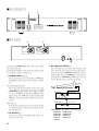
■
Face avant
■
Face arrière
Le bloc d’alimentation PW3000MA doit être installé dans
un endroit bien aéré.
Evitez surtout de bloquer les faces avant et arrière car la
voie de ventilation passe par l’avant et l’arrière.
A
Commutateur
POWER ON/OFF
Après avoir effectué les connexions avec la console de
mixage, actionnez ce commutateur pour alimenter la
console.
B
Contrôle de fonctionnement
Ces témoins indiquent l’état de fonctionnement des
quatre sources d’alimentation fournie à la console de
mixage. Normalement (s’il n’y a pas de problème), les
témoins verts s’allument (NORMAL). S’il y a un pro-
blème, le témoin de la section concernée s’éteint.
Coupez l’alimentation, attendez un certain temps et
remettez le bloc sous tension. Si le ou les mêmes
témoins sont toujours éteints, contactez un SAV
Yamaha.
C
Borne GND (masse)
Cette borne accueille la vis de mise à la masse. S’il y a
du bruit ou des bourdonnements, mettez l’appareil à
la masse via cette borne ou en le reliant au châssis de
l’autre appareil.
D
Connecteur
DC OUTPUT
Reliez ce connecteur à la console de mixage afin de
l’alimenter.
E
Connecteur
DC PARALLEL INPUT
Ce connecteur permet de brancher deux PW3000MA
en parallèle. Comme l’illustration suivante l’indique,
servez-vous du câble de connexion parallèle fourni
pour effectuer les branchements. Dans ce cas, chaque
PW3000MA fournit 50% de l’alimentation. Dans
l’éventualité peu probable qu’un des PW3000MA
tombe en panne, l’autre PW3000MA fournit alors
100% des besoins, garantissant ainsi une alimentation
ininterrompue.
L’alimentation PW3000MA convient pour les
modèles suivants:
M2500-56C M3000A-56C
M2500-48C M3000A-40C
M2500-40C M3000A-32
M2500-32 M3000A-24
M2500-24
POWER
OPERATION MONITOR
POWER SUPPLY
ON/ OFF
NORMAL
+48V +12V +15V –15V
1 2
DC OUTPUT
CONNECT
DISCONNECT
PIN 2 +15V 5.0A
PIN 5
–15V 5.0A
PIN 6 +12V 5.0A
PIN 9 +48V 0.2A
DC PARALLEL INPUT
CONNECT
DISCONNECT
5 4
3
DC OUTPUT
CONNECT
DISCONNECT
PIN 2 +15V 5.0A
PIN 5
–15V 5.0A
PIN 6 +12V 5.0A
PIN 9 +48V 0.2A
DC PARALLEL INPUT
CONNECT
DISCONNECT
DC OUTPUT
CONNECT
DISCONNECT
PIN 2 +15V 5.0A
PIN 5
–15V 5.0A
PIN 6 +12V 5.0A
PIN 9 +48V 0.2A
DC PARALLEL INPUT
CONNECT
DISCONNECT
PW3000MA
PW3000MA
DC POWER
INPUT
DC OUTPUT
DC OUTPUT
DC PARALLEL
INPUT

11
■
Fiche technique
■
Configuration des broches du cordon d’alimentation
■
Dimensions
• Les caractéristiques techniques et l’aspect extérieur peuvent être modifiés sans avis préalable.
Alimentation USA et Canada: 120 V, 60 Hz
Europe: 230 V, 50 Hz
Autres: 240 V, 50 Hz
Consommation USA et Canada: 500 W, 600 VA
Europe: 500 W
Autres: 500 W
Dimensions (L x H x P) 480 mm x 103,5 mm x 455 mm
Poids 15 kg
Accessoires Câble de connexion parallèle (1 m)
Broche no. Signal
Connecteur d’alimentation
1 Alimentation (distance)
2 +15 V
3
±
15 V masse
4 +48 V masse
5 –15 V
6 +12 V
7 +12 V masse/ alimentation (distance)
8 Alimentation (distance)
9 +48 V
10 Masse au cadre
DC OUTPUT
DC PARALLEL INPUT
123
8910
5467
321
1098
6754
P:455
L:480
88
H:103.5
56.8 292
308
49.4 405.6
Unités: mm

POWER SUPPLY
Bedienungsanleitung
Deutsch

15
■
Vorsichtsmaßnahmen
• Schließen Sie das Stromkabel der Stromversorgung
ausschließlich an eine Steckdose an, die den Anforde-
rungen in der
Bedienungsanleitung
oder auf dem
Typenschild entspricht. Sonst besteht nämlich Brand-
oder Schlaggefahr.
• Verwenden Sie die Stromversorgung nicht an extrem
warmen Orten bzw. in der prallen Sonne, weil sonst
Brandgefahr besteht.
• Stellen Sie die Stromversorgung nicht an extrem stau-
bige oder feuchte Orte, weil dann Brand- oder Schlag-
gefahr besteht.
• Schließen Sie niemals mehrere Geräte an dieselbe
Steckdose an. Das könnte die Steckdose nämlich über-
fordern, so daß es zu einem Kurzschluß bzw. Brand
kommt.
• Stellen Sie keine schweren Gegenstände auf das Netz-
kabel, um Kurzschlüsse und Brandgefahr zu vermei-
den.
• Wenn das Netzkabel beschädigt ist (z.B. wenn eine
Ader durchtrennt ist oder blank liegt), bitten Sie Ihren
Händler um ein neues Kabel. Wenn Sie nämlich das
beschädigte Kabel verwenden, bestehen Kurzschluß-
und Brandgefahr.
• Ziehen Sie beim Lösen des Netzanschlusses immer am
Stecker und niemals am Kabel. Sonst könnten näm-
lich die Adern reißen, so daß Kurzschluß- und Brand-
gefahr bestehen.
• Legen Sie keine kleinen Metallgegenstände auf die
Stromversorgung. Wenn diese Gegenstände nämlich
ins Geräteinnere gelangen, bestehen Kurzschluß- und
Brandgefahr.
• Versperren Sie niemals die Lüftungsschlitze der
Stromversorgung. Diese befinden sich auf der Vorder-
seite und sorgen für die notwendig Kühlung. Wenn
Sie die Lüftungsschlitze versperren, kann es zu einem
Wärmestau und sogar Brand kommen.
• Sorgen Sie für ausreichend Freiraum um die Strom-
versorgung herum.
• Wenn Sie die Stromversorgung in ein Rack einbauen,
sollten Sie über und hinter dem Gehäuse einen Frei-
raum von mindestens 10cm lassen. Während der Ver-
wendung der Stromversorgung müssen Sie entweder
die Rückseite der Flightcase entfernen oder ihre Lüf-
tungsschlitze öffnen, um Wärmestaus und daraus sich
ergebende Brandgefahr zu vermeiden.
• Modifizieren Sie die Stromversorgung niemals selbst.
Das kann nämlich zu schweren Schäden führen.
Außerdem erlischt der Garantieanspruch.
• Die Stromversorgung darf bei einer Umgebungstem-
peratur von 5
°
C bis 35
°
C betrieben werden.
• Schalter Sie das Pult sowie alle daran angeschlossenen
Geräte aus, bevor Sie die Stromversorgung mit dem
Pult verbinden. Siehe die Bedienungsanleitung der
übrigen Geräte. Verwenden Sie ausschließlich geeig-
nete Kabel.
• Fällt Ihnen etwas Abnormales an der Stromversor-
gung auf –z.B. Rauch, starker Geruch oder übertriebe-
nes Rauschen–, müssen Sie sie sofort ausschalten.
Lösen Sie den Netzanschluß und überprüfen Sie, ob
das Problem damit behoben ist. Reichen Sie die
Stromversorgung anschließend zur Reparatur ein.
Verwenden Sie sie auf keinen Fall weiter.
• Wenn Fremdkörper oder Flüssigkeiten ins Gerätein-
nere gelangen, müssen Sie die Stromversorgung sofort
ausschalten. Lösen Sie den Netzanschluß und reichen
Sie die Stromversorgung zur Reparatur ein. Verwen-
den Sie sie auf keinen Fall weiter.
• Wenn Sie die Stromversorgung längere Zeit nicht ver-
wenden möchten, sollten Sie den Netzanschluß lösen,
um sie bei Gewitter nicht unnötig Blitzeinschlag usw.
auszusetzen.
• Verwenden Sie zum Reinigen der Stromversorgung
niemals Waschbenzin, Reinigungsmittel oder chemi-
sche Tücher. Säubern Sie sie mit einem trockenen,
weichen Tuch.
• Diese Stromversorgung enthält hochfrequente Digi-
tal-Schaltkreise, die den Radio- oder Fernsehempfang
stören können. Stellen Sie sie niemals in die Nähe sol-
cher Geräte.
Für das europäische Modell
Kunden-/Benutzerinformation nach EN55103-1 und
EN55103-2.
Eingangsstrom: 44A
Entspricht den Umweltschutzbestimmungen: E1, E2, E3
und E4.

16
■
Frontplatte
■
Rückseite
Die Stromversorgung der PW3000MA sollte an einem gut
belüfteten Ort betrieben werden. Versperren Sie niemals
die Lüftungsschlitze oder Rückseite, um einen optimalen
Luftstrom zu gewährleisten.
A
POWER ON/OFF
-Schalter
Schließen Sie die PW3000MA zuerst an das Pult an
und drücken Sie anschließend diese Taste, um das Pult
ein- und wieder auszuschalten.
B
Betriebsanzeigen
Diese vier Dioden zeigen den Status der vier Span-
nungsquellen für das Mischpult an. Normalerweise
(d.h. wenn alles nach Plan läuft) leuchten die grünen
Dioden (NORMAL). Tritt ein Fehler, so erlischt die
Diode des betreffenden Schaltkreises. Schalten Sie die
Stromversorgung dann unverzüglich aus und warten
Sie ein paar Minuten, bevor Sie sie wieder einschalten.
Leuchtet die betreffende Diode dann immer noch
nicht, reichen Sie die PW3000MA zur Reparatur ein.
C
GND-Schraube
Hiermit können Sie die PW3000MA erden, indem Sie
hier ein Erdungskabel anschließen oder eine Verbin-
dung mit dem Chassis eines anderen Gerätes herstel-
len, was z.B. bei Brummschleifen notwenig ist.
D
DC OUTPUT
-Anschluß
Verbinden Sie diesen Anschluß mit dem Mischpult,
um es mit Strom zu versorgen.
E
DC PARALLEL INPUT
-Anschluß
Über diese Buchse können Sie eine zweite
PW3000MA parallel anschließen. Nehmen Sie dabei
die nachstehend gezeigten Anschlüsse vor. In dem Fall
liefern beide PW3000MA-Einheiten dann 50% des
Strombedarfs. Falls eine der beiden PW3000MA uner-
wartet ausfallen sollte, liefert die andere automatisch
100% des Strombedarfs, so daß peinliche Ausfälle ver-
mieden werden.
Die PW3000MA Stromversorgung eignet sich für
folgende Modelle:
M2500-56C M3000A-56C
M2500-48C M3000A-40C
M2500-40C M3000A-32
M2500-32 M3000A-24
M2500-24
POWER
OPERATION MONITOR
POWER SUPPLY
ON/ OFF
NORMAL
+48V +12V +15V –15V
1 2
DC OUTPUT
CONNECT
DISCONNECT
PIN 2 +15V 5.0A
PIN 5
–15V 5.0A
PIN 6 +12V 5.0A
PIN 9 +48V 0.2A
DC PARALLEL INPUT
CONNECT
DISCONNECT
5 4
3
DC OUTPUT
CONNECT
DISCONNECT
PIN 2 +15V 5.0A
PIN 5
–15V 5.0A
PIN 6 +12V 5.0A
PIN 9 +48V 0.2A
DC PARALLEL INPUT
CONNECT
DISCONNECT
DC OUTPUT
CONNECT
DISCONNECT
PIN 2 +15V 5.0A
PIN 5
–15V 5.0A
PIN 6 +12V 5.0A
PIN 9 +48V 0.2A
DC PARALLEL INPUT
CONNECT
DISCONNECT
PW3000MA
PW3000MA
DC POWER
INPUT
DC OUTPUT
DC OUTPUT
DC PARALLEL
INPUT

17
■Spezifikationen
■Bedrahtung der Stromversorgungsbuchsen
■Abmessungen
• Änderungen der technischen Daten ohne Vorankündigung vorbehalten.
Stromanforderungen USA und Kanada: 120 V, 60 Hz
Europa: 230 V, 50 Hz
Audere Länder: 240 V, 50 Hz
Leistungsaufnahme USA und Kanada: 500 W, 600 VA
Europa: 500 W
Audere Länder: 500 W
Abmessungen (B x H x T) 480 mm x 103,5 mm x 455 mm
Gewicht 15 kg
Lieferumfang Parallelanschlußkabel (1 m)
Stiftnr. Signalname
Stromversorgungsbuchsen
1 Externe Stromversorgung
2 +15 V
3 ±15 V GND
4 +48 V GND
5 –15 V
6 +12 V
7 +12 V GND/ Externe Stromversorgung
8 Externe Stromversorgung
9 +48 V
10 FRAME GND
DC OUTPUT
DC PARALLEL INPUT
123
8910
5467
321
1098
6754
T:455
B:480
88
H:103.5
56.8 292
308
49.4 405.6
Einheit: mm

POWER SUPPLY
V445680 R1 1 IP 24
NP Printed in Taiwan
M

2
!

3
!

4
POWER
OPERATION MONITOR
POWER SUPPLY
ON/ OFF
NORMAL
+48V +12V +15V –15V
1 2
DC OUTPUT
CONNECT
DISCONNECT
PIN 2 +15V 5.0A
PIN 5
–15V 5.0A
PIN 6 +12V 5.0A
PIN 9 +48V 0.2A
DC PARALLEL INPUT
CONNECT
DISCONNECT
5 4
3
1 POWER ON/OFF
2
3
4 DC OUTPUT
5 DC PARALLEL INPUT
DC OUTPUT
CONNECT
DISCONNECT
PIN 2 +15V 5.0A
PIN 5
–15V 5.0A
PIN 6 +12V 5.0A
PIN 9 +48V 0.2A
DC PARALLEL INPUT
CONNECT
DISCONNECT
DC OUTPUT
CONNECT
DISCONNECT
PIN 2 +15V 5.0A
PIN 5
–15V 5.0A
PIN 6 +12V 5.0A
PIN 9 +48V 0.2A
DC PARALLEL INPUT
CONNECT
DISCONNECT
PW3000MA
PW3000MA
DC POWER
INPUT
DC OUTPUT
DC OUTPUT
DC PARALLEL
INPUT

5
DC OUTPUT
DC PARALLEL INPUT
123
8910
5467
321
1098
6754
D:455
W:480
88
H:103.5
56.8 292
308
49.4 405.6

☎
☎
☎
☎
☎
☎
☎
☎
☎
☎
☎
☎
☎
☎
☎
☎
☎
☎
-
 1
1
-
 2
2
-
 3
3
-
 4
4
-
 5
5
-
 6
6
-
 7
7
-
 8
8
-
 9
9
-
 10
10
-
 11
11
-
 12
12
-
 13
13
-
 14
14
-
 15
15
-
 16
16
-
 17
17
-
 18
18
-
 19
19


Yamaha PW3000MA Uživatelský manuál
- Kategorie
- Napájecí zdroje
- Typ
- Uživatelský manuál
v jiných jazycích
- polski: Yamaha PW3000MA Instrukcja obsługi
- español: Yamaha PW3000MA Manual de usuario
- italiano: Yamaha PW3000MA Manuale utente
- Deutsch: Yamaha PW3000MA Benutzerhandbuch
- svenska: Yamaha PW3000MA Användarmanual
- português: Yamaha PW3000MA Manual do usuário
- français: Yamaha PW3000MA Manuel utilisateur
- 日本語: Yamaha PW3000MA ユーザーマニュアル
- Türkçe: Yamaha PW3000MA Kullanım kılavuzu
- English: Yamaha PW3000MA User manual
- dansk: Yamaha PW3000MA Brugermanual
- русский: Yamaha PW3000MA Руководство пользователя
- Nederlands: Yamaha PW3000MA Handleiding
- română: Yamaha PW3000MA Manual de utilizare