Hendi 272404 Uživatelský manuál

Typ
Uživatelský manuál
You should read this user manual carefully before
using the appliance.
Bevor Sie das Gerät in Betrieb nehmen, sollten
Sie diese Gebrauchsanweisung aufmerksam lesen.
Alvorens de apparatuur in gebruik te nemen dient
u deze gebruiksaanwijzing aandachtig te lezen.
Przed uruchomieniem urządzenia należy koniecznie
dokładnie przeczytać niniejszą instrukcję obsługi.
Lisez attentivement ce mode d’emploi avant d’utiliser
l’appareil .
Prima di utilizzare l’apparecchio in funzione leggere
attentamente le istruzioni per l’uso.
Citiţi cu atenţie prezentul manual de utilizare înainte
de folosirea aparatului.
Внимательно прочитайте руководство пользователя
перед использованием прибора.
Πρέπει να διαβάσετε αυτές τις οδηγίες χρήσης
προσεκτικά πριν χρησιμοποιήσετε τη συσκευή.
Před použitím spotřebiče si pečlivě přečtěte tuto
uživatelskou příručku.
Pred použitím tohto spotrebiča si pozorne prečítajte
tento návod pre používateľov.
A készülék használata előtt figyelmesen olvassa el
ezeket a használati utasításokat.
Prije uporabe uređaja pažljivo pročitajte ovaj
korisnički priručnik.
PYRAMID HEATER
272404
2
Keep these instructions with the appliance.
Diese Gebrauchsanweisung bitte beim Gerät aufbewahren.
Bewaar deze handleiding bij het apparaat.
Zachowaj instrukcję urządzenia.
Conservate le istruzioni insieme all’apparecchio.
Păstraţi maualul de utilizare alături de aparat.
Tento návod si odložte so spotrebičom.
Хранить руководство вместе с устройством.
Φυλάξτε αυτές τις οδηγίες μαζί με τη συσκευή.
Uchovávejte tuto příručku se spotřebičem.
Tento návod si odložte so spotrebičom.
Ezeket az utasításokat tartsa a készülék mellett.
Čuvajte ove upute s uređajem.
Use outdoors only.
Nur im Freien verwenden.
Alleen buiten gebruiken.
Stosować tylko na wolnej przestrzeni.
A n’utiliser qu’à l’extérieur des locaux.
Può essere utilizzato solo all’aperto.
A se folosi doar spații deschise.
Использовать на открытом воздухе.
Για χρήση μόνο σε εξωτερικό χώρο.
Používat výhradně venku.
Používajte iba vo vonkajšom prostredí.
Használat után zárja el a gázellátást a gázpalacknál.
Zatvorite dovod plina na plinskom cilindru nakon uporabe.
size : 215mm X 70mm
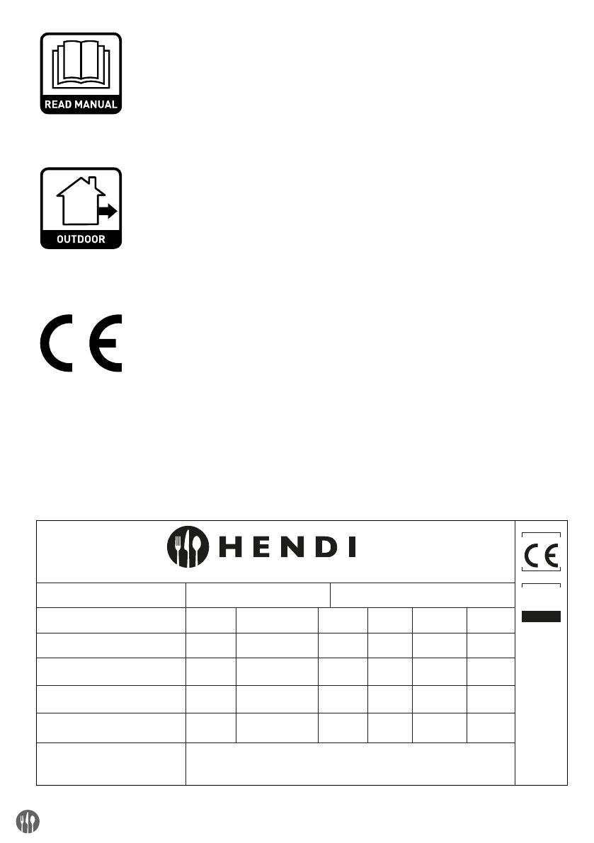
[HS] 11,2 kW [HS] 9,5 kW
815 g/h 643 g/h
G31-50 mbar G30/31-37 mbar
NL/DE/AT/CH BE/FR/LU/GB/IE/GR/IT
[HS] 9,5 kW
691 g/h
G30/31-
30 mbar
RO/IT/HU
272404 Pyramid Heater PIN : 0063CO7365
[HS] 9,5 kW
G30: 691 g/h,
G31: 679g/h
G30-28-30 mbar,
G31-37 mbar
CZ/SK
[HS] 12,5 kW
900 g/h
G31-50 mbar
AT/CH/HR
I3P I3P I3B/P I3B/P I3+
[HS] 11,2 kW
815 g/h
G30/31-37
mbar
PL
I3B/P
Item / Artike l/ Item / Artykuł / Article / Articolo / Articol / пункт /
Στοιχείο / Číslo artiklu / Číslo artikla / Tétel / Stavka
Country / Land / Land / Kraj / Payes / Paese / țară / страна / Χώρα /
Země / Krajina / Ország / Država
Category / Categorie / Kategorie / Kategoria / Catégorie / Categoria /
Categorie / категория / Κατηγορία / Kategorie / Kategória / Kategória /
Kategorija
Power / Belasting / Leistung / Moc nominaina / Puissance / Potenza /
Putere / Мощность / Ισχύς / Výkon / Výkon / Áramellátás /Snaga
Set up / Auflegung / Inrichting / Przeznaczony na / Conçu pour /
Configurare / Configurarea / Настройка / Ρύθμιση / Hodnota
regulátoru tlaku / Hodnota regulátora tlaku /Beüzemelés / Postavljanje
Consumption / Verbrauch / Verbruik / Zuzycie / Consommation /
Consumo / Consum / потребление / Κατανάλωση / Spotřeba /
Spotreba / Fogyasztás / Potrošnja
Serial no. / Serien nr. / Serie nr. / Nr. seryjny / N°de série /
N° seriale / Număr serial / Серийный номер / Αριθμός
σειράς / Pořadové číslo / Poradové číslo / Sorozatszám /
Serijski br.
A se folosi doar spații deschise.
Citiți cu atenție instrucțiunile înainte de utilizarea aparatului.
AVERTISMENT: piesele accesibile pot fi foarte fierbinți.
A nu se lăsa la îndemâna copiilor.
Use outdoors only.
Read the instructions before using the appliance.
WARNING: accessible parts may be very hot.
Keep young children away.
Nur im Freien verwenden.
Lesen Sie die Bedienungsanleitung vor Inbetriebnahme des Gerätes.
ACHTUNG: Zugängliche Teile können sehr heiß sein.
Kinder fernhalten.
Alleen buiten gebruiken.
Lees de instructies voor ingebruikname.
WAARSCHUWING: Aanraakbare delen kunnen erg heet zijn.
Houdt jonge kinderen op afstand.
A n'utiliser qu'à l'extérieur des locaux.
Consulter la notice avant l'utilisation.
ATTENTION : des parties accessibles peuvent être très chaudes.
Eloigner les jeunes enfants.
Για χρήση μόνο σε εξωτερικό χώρο.
Διαβάστε τις οδηγίες πριν χρησιμοποιήσετε τη συσκευή.
ΠΡΟΕΙΔΟΠΟΙΗΣΗ: τα προσβάσιμα σημεία μπορούν να
θερμανθούν υπερβολικά.
Διατηρείτε τη συσκευή μακριά από παιδιά.
Использовать на открытом воздухе.
Перед использованием устройства прочитайте,
пожалуйста, руководство по обслуживанию.
ВНИМАНИЕ: Детали устройства могут быть горячими.
Убедитесь в том, что рядом с устройством нет детей.
Csak kültéri használatra.
A készülék használata előtt olvassa el a használati utasítást.
FIGYELEM: az alkatrészek forrók lehetnek.
Gyermekektől távol tartandó.
Isključivo za upotrebu na otvorenom.
Prije upotrebe uređaja pročitajte upute.
UPOZORENJE: dostupni dijelovi mogu biti jako vrući.
Ne smije se dopustiti pristup djeci.
Stosować tylko na wolnej przestrzeni.
Przeczytaj instrukcję przed użyciem urządzenia.
OSTRZEŻENIE: dostępne części urządzenia mogą być bardzo gorące.
Trzymaj dzieci z dala od urządzenia.
Può essere utilizzato solo all'aperto.
Prima dell'uso leggere attentamente le istruzioni d'uso.
AVVERTENZE! I componenti del dispositivo possono essere molto
caldi.
Assicurarsi che non ci siano bambini nelle vicinanze del dispositivo.
Pouze pro venkovní použití.
Před použitím přístroje si přečtěte návod na použití.
POZOR: Přístupné části mohou být velmi horké.
Udržujte mimo dosah dětí.
Len pre vonkajšie použitie.
Pred použitím prístroja si prečítajte návod na použitie.
POZOR: Prístupné časti môžu byť veľmi horúce.
Udržujte mimo dosah detí.
Innovatielaan 6, 6745 XW De Klomp,The Netherlands www.hendi.eu
0063/21
ALUMINIUM
AL
0063/XX
3
EN
Dear Customer,
Thank you for purchasing this Hendi appliance. Please read this manual carefully before connecting the
appliance in order to prevent damage due to incorrect use. Read the safety regulations in particular very
carefully.
Safety regulations
This appliance must be used outdoors or in a well ventilated area, and should not be
installed or used indoors.
Change the gas cylinder in a well ventilated area, away from any inflammation sources.
The cylinder must be stored outdoors or in a well ventilated area.
Storage this appliance indoors is permissible only if gas cylinder is disconnected and
removed from the appliance.
Do not move this appliance when in operation, or after it has been turned off before the
temperature has cooled down.
Do not attempt to alter the appliance in any manner. Do not paint the radiant screen,
control panel or reflector.
Do not obstruct the ventilation holes of the cylinder housing.
The appliance must be installed and gas cylinder stored in accordance with local gas
fitting regulations.
Shut off the valve at the gas cylinder or the regulator before moving the appliance.
Use only the type of gas specified by the manufacturer.
Repairs should be done by a qualified person.
In case of violent wind, particular attention must be taken against tilting of the appliance.
Check that the regulator seal is correctly fitted and able to fulfil its function.
Close the gas supply at the valve of the gas cylinder or the regulator after use.
Do not use this appliance until all connections have been leak tested.
In the event of gas leakage, the appliance shall not be used or if alight, the gas supply
shall be shut off and the appliance shall be investigated and rectified before it is used
again.
Checking the tubing or the flexible hose per month and each time the cylinder is changed.
The tubing or the flexible hose must be changed within the prescribed intervals or with
-
in one year. The flexible hose should not extended than 1.5m according to standard
EN16436:2014.
The hose assembly must be replaced prior to the appliance being put into operation if
there is evidence of excessive abrasion or wear, or if the hose is damaged, and that the
replacement hose assembly shall be that specified by the manufacturer.
The heater should be inspected before use and at least annually by a qualified service
person. More frequent cleaning may be required as necessary. It is imperative that control
compartment, burners and circulating air passageways of the appliance be kept clean.
Shut off and check heater immediately if any of the following conditions exist:
¨ The smell of gas in conjunction with extreme yellow tipping of the burner flames.
4
EN
¨ Heater does not reach a proper temperature. A temperature less than 5ºC will cause
restricted heat flow and the appliance will not work properly.
¨ The appliance starts making popping noises during use (a slight popping noise is nor
-
mal when the appliance is extinguished).
The regulator & hose assembly must be located out of pathways where people may trip
over it or in area where the hose will not be subject to accidental damage.
Any guard or other protective device removed for servicing the heater must be replaced
before operating the heater.
Children and adults should be warned of the hazards of high surface temperatures and
should stay away to avoid burns or clothing ignition.
Young children and pets should be carefully supervised when they are in the area of the
heater.
Clothing or other flammable materials should not be hung from the appliance, or placed
on or near the appliance.
Do not place articles on or against this appliance. Certain material or items when stored
under or near this appliance will be subjected to radiant heat and could be seriously
damaged.
Do not use or store flammable materials near this appliance.
Do not spray aerosols in the vicinity of this appliance while it is in operation.
Always maintain at least 0.9m clearance from combustible materials.
Always position the appliance on a firm level surface. An amply ventilated area must have
a minimum of 25% of the surface area open. The surface area is the sum of the walls
surface.
The injector in this appliance is not removable and the injector is only assembled by
manufacture. This appliance is forbidden to convert from one gas pressure to another
pressure.
Do not connect the gas cylinder directly to the appliance without regulator.
The gas cylinder must be fixed by cylinder belt, which is inside the housing, while
installation.
Intended use
The device is intended for professional use and
can be operated only by qualified personnel.
The appliance is designed only for heating out-
doors or well ventilated areas. Any other use may
lead to damage to the appliance or personal in-
jury.
Operating the appliance for any other purpose
shall be deemed a misuse of the device. The user
shall be solely liable for improper use of the de-
vice.
5
EN
Patio heater part list
PART # PART NAME PICTURE QTY
A Reflector
1
B Flame screen
1
C Mesh guard - upper
4
D Mesh guard - lower
4
E Support bar - upper
4
F Support bar - lower
4
G Glass tube
2
H Connection glass tube
1
I Rubber ring
1
J Burner assembly
K Tank housing assembly
1
L Chain (assembled with door)
1
Hardware
PART # PART NAME PICTURE QTY DESCRIPTION
AA M6 cap nut
4 To connect reflector and flame screen.
BB
Standard screws &
washer
4
M5 x 8 screw & M5 washer.
To fix burner assembly on the tank housing
assembly.
6
EN
Exploded view
7
EN
Patio heater assembly
Assembly instructions
• List of Required Tools: Philip Screwdriver
Leak Detection Solution one part detergent and
three parts water
Assemble all nuts and bolts loosely at first.
Tighten all connections after completion of as-
sembly. This eases your work and increase the
stability of the appliance.
Before assembly, make sure all packing material
and any transmit protection must be removed.
Small deviations in equipment may occur. This is
no lack of quality but subject to improvements.
If any part is missing or damaged, do not attempt
to assembly this product, Contact customer ser-
vice for replacement parts.
Assembly should be performed on a flat, level,
non-abrasive surface.
ESTIMATED ASSEMBLY TIME: 45 minutes.
STEP 1: Lie down tank housing assembly (K). Open door
and take out all parts.
STEP 2: Keep tank housing in lie down position. Fix the
burner assembly (J) to tank housing by using 4pcs
Standard Screws and Washers (BB).
STEP 3: Unscrews 2pcs Standard screws and washers (BB) from a Support Bar – Lower (F). Insert Support Bar - Upper (E)
to Support Bar - Lower (F) and fix by using 2pcs Standard screws and washers (BB). Repeat this step to connect
left 3sets support bars.
8
EN
STEP 4: Unscrewing 2pcs Standard Screws and Washers (BB) as arrow showed from Support Bar – UPPER (E). Attach
Flame Screen (B) to the top of Whole Support Bar and fix by using 2pcs standard screws and washers. Repeat this
step to connect Flame Screen (B) with left 3sets Whole Support Bar.
STEP 5: Place Reflector (A) on the Flame Screen (B) and fix
by using 4pcs M6 CAP NUT (AA).
STEP 6: Unscrews 8pcs Standard Screws and Washers (BB) from top of tank housing assembly (K). Lift the assembled
upper parts of heater and place them on the tank housing. Push support bar as photo showed and make sure
each support bar inserts into slot. Fix at bottom position by using 8pcs standard screws and washers (BB).
9
EN
STEP 7: Align and insert Mesh Guard – Lower (D) into the inside slots of Support Bar – Lower (F). Repeat this step to insert
2pcs Mesh Guard – Lower (D).
STEP 8: Unload 4PCS Guard Fastening Plates by un-
screwing 4PCS screws and washers from
FLAME SCREEN (B).
STEP 9: Same as Step 7 to align and Insert 3pcs Mesh Guard – Upper (C) into the inside slots of 3pcs Support Bar – Upper
(E).
10
EN
STEP 10: Hold Glass Tube (G) and insert one side of Glass Tube into Flame Screen (B) until touching the top of Flame
Screen, then Insert another side of Glass Tube (G) into center of Tank Housing (top of Burner Assembly).
NOTE: GLASS TUBE IS A FRAGILE PART, ASSEMBLE GLASS TUBE CAREFULLY AND SLOWLY!
STEP 11: Repeat Step 7 and step 9 to assemble the last
Mesh Guard – Lower (D) and Mesh Guard – Up-
per (C). Replace 4pcs Guard Fastening Plates on
the FLAME SCREEN (B) used 4pcs screws and
washers.
STEP 12: Insert & Fix the door to Tank Housing Assembly
(K), then attach the Chain (L) to Burner Assembly
(J).
Warning: when Butune gas is used under the working pressure of 50mbar, the ring of flame screen (part
B) must be removed.
11
EN
Operating instructions
Before first use and after every gas cylinder change, gas delivery system must be purged of air before
igniting! To do this, turn the control knob anti-clockwise to the pilot setting. Press knob in and hold for 3
minutes before attempting ignition.
Battery replacment
Remove impulse ignition cap from Burner Assem-
bly (J) by turning cap counterclockwise. Install 1
AAA battery. Negative end of battery goes in first,
then replace impulse ignition cap by turning cap
clockwise.
To light the pilot
• Check all connections prior to each use.
• Turn on main gas supply at source.
Press to turn control knob anti-clockwise to
PILOT, see right photo.
Hold knob depressed, press IGNITION button re-
peatedly until pilot flame is lit, then continue to
hold the knob depressed for 10 seconds until the
pilot remains it after releasing knob.
If pilot fails to ignite or alight, press to turn knob
clockwise to OFF and repeat.
To light the patio heater
The pilot should be lit and the knob set to PILOT.
Hold knob depressed gently and turn anti-clock-
wise to LOW.
When mesh glows lit, turn knob clockwise from
Low to HIGH as needed.
Note: The burner may be noisy when initially
turned on. To eliminate excessive noise from the
burner, turn the control knob to the pilot position.
Then turn the knob to the level of heat desired.
Re-lighting
Turn Control Knob to OFF.
Wait at least 5 minutes, to let gas dissipate, be-
fore attempting to re-light pilot.
Repeat the “Lighting” steps.
To extinguish
Hold knob depressed & turn the knob clockwise
to ‘OFF’
Close the valve of the gas cylinder or the regula-
tor after use.
Close the gas bottle and allow this appliance to
cool before moving the appliance.
Note: After use, some discoloration of the emitter
screen is normal. Close regulator after use, allow
the appliance to cool before moving.
12
EN
Leak testing
Never use a naked flame to check for leaks.
Never leak test while smoking.
The gas connections on this appliance are leak
tested at the factory prior to shipment.
This appliance needs to be periodically checked
for leaks and an immediate check is required if the
smell of gas is detected.
Make a soap solution using 1 part of liquid
dish-washing soap to 3 parts water. The soap
solution can be applied with a soap bottle, brush,
or rag to the leak tested points shown in the fig-
ure above.
The valve of the gas cylinder should be in the OFF
position at this point of the leak test. Once the
soapy solution is applied to the gas connections,
the valve of the gas cylinder needs to be turned to
the ON position.
Soap bubbles will begin to form in the soapy solu-
tion if a leak is present.
In case of a leak, turn off the gas supply. Tighten
any leaking fittings, then turn the gas supply on
and recheck.
Leak Test Point 1 2 3 4
1
3
4
2
Gas requirements
Never use a gas cylinder with a damaged body,
valve, collar, or foot ring. A dented or rusty gas
tank may be hazardous and should be checked
out by a gas supplier.
Never connect this appliance to an unregulated
gas source.
When the appliance is not in use, turn the gas
cylinder OFF.
Always perform a leak test on gas connections
whenever a cylinder is connected. If bubbles form
in the leak test solution, do not use. Never use a
flame to test for leaks.
Connecting to a gas cylinder
Recommended to use 9 kg gas cylinder or refer
to your gas supplier for suitable gas cylinder.
Approved gas regulator is used according to ap-
pliances categories and countries listed in data
plate. Approved flexible hose would be changed
when the national conditions require it & consult
the local regulations, these may differ.
Warning: assembly of the tubing must be con-
ducted by some qualified tuber of destination
countries.
Only change gas cylinders outdoors or in a well
ventilated area away from naked flames and any
other source of ignition (candle, cigarettes, other
flame producing appliance….).
The gas cylinder must always be used in an up-
right position.
Close the heater control knob by turning fully
clockwise.
Close the gas cylinder tap and then attach the
regulator onto the gas cylinder.
Tighten all connections firmly and with a spanner
where appropriate. The cylinder should be locat-
ed on the cylinder base.
The gas cylinder must be fixed by cylinder belt,
which is inside the housing, while installation.
Check for leaks at all joints using soapy water. If
a leak is found, tighten the joint and then re-test.
13
EN
Securing the gas cylinder
Fix both brackets of Velcro tapes onto the base
using 4pcs M6*12 bolts, M6 washer and M6nuts.
Position a gas cylinder inside the tank housing.
Connect the gas cylinder with a regulator. Please
refer to the instructions attached with the regu-
lator on how to connect a regulator with the gas
cylinder.
Stick Velcro tapes together as above photo illus-
trated. The tapes must be in a proper tightness
for the gas cylinder.
Caution: Please take care that the Velcro tapes.
DO NOT strain the regulator assembly.
Important safety rules
For use outdoors or in amply ventilated areas.
An amply ventilated area must have a minimum of
25% of the surface area open. The surface area is
the sum of the walls surface.
The use of this appliance in enclosed areas can be
dangerous and is PROHIBITED.
Children and adults should be aware of the high op-
erating temperatures of areas above the post when
operating this heater. Children should be carefully
supervised when in the vicinity of the heater.
NEVER hang anything, including clothes or any
other flammable items, on this heater.
DO NOT operate this heater unless it is fully as-
sembled with its reflector in place. Respect the
minimum clearances from combustible materials.
14
EN
Maintenance
To enjoy years of outstanding performance from
your heater, make sure you perform the following
maintenance activities on a regular basis:
Keep exterior surfaces clean.
Use warm soapy water for cleaning. Never use
flammable or corrosive cleaning agents.
While washing your unit, be sure to keep the area
around the burner and pilot assembly dry at all
times. If the gas control is exposed to water in
any way, DO NOT try to use it. It must be replaced.
Airflow must be unobstructed. Keep controls,
burner and circulation air passageways clean.
Signs of possible blockage include:
Gas odor with extreme yellow tipping of flame.
Heater does NOT reach the desired temperature.
Heater glow is excessively uneven.
Heater makes popping noises.
Spiders and insects can nest in burner or orifices.
This dangerous condition can damage the heater
and render it unsafe for use. Clean burner holes
by using a heavy duty pipe cleaner. Compressed
air may help clear away smaller particles.
Carbon deposits may create a fire hazard. If any
carbon deposits develop, clean dome and engine
with warm soapy water.
Note: in a salt-air environment (such as near the
sea), corrosion occurs more quickly than normal.
Frequently check the corroded areas and repair
them promptly.
Servicing
Please consult your local dealer for servicing this
appliance and replacement of its parts. The ser-
vicing of the appliance shall be carried out only by
authorised personnel.
Caution: do not use unauthorized parts or com-
ponents for this appliance, only use original
equipment replacement parts and components.
The use of unauthorized parts or components
will void the warranty and can create an unsafe
condition.
Storage
There is no limitation on the storage of the appli-
ance indoors provided that the cylinder is removed
from the appliance.
Between uses:
Turn control knob OFF.
Turn gas cylinder OFF.
Store heater upright in an area sheltered from di-
rect contact with inclement weather (such as rain,
sleet, hail, snow, dust and debris).
If desired, cover to protect exterior surfaces and to
prevent build up in air passages.
Note: Wait until heater is cool before covering.
During periods of extended inactivity or when
transporting:
Turn control knob OFF.
Disconnect gas cylinder and move to a secure,
well ventilated location outdoors. DO NOT store
in a location that will exceed 50°C.
Store heater upright in an area sheltered from di-
rect contact with inclement weather (such as rain,
sleet, hail, snow, dust and debris).
If desired, cover heater to protect exterior surfaces
and to prevent build up in air passages.
Note: Wait until heater is cool before covering
Troubleshooting
IF THE PROBLEM IS AND THIS CONDITION EXISTS THEN DO THIS
Pilot won’t light
Cylinder valve is closed Open valve
Blockage in orifice or pilot tube Clean or replace orifice or pilot tube
Air in the gas line
Open gas line and bleed it (pressing control knob in)
for not more than 1-2 minutes or until you smell gas
Low gas pressure
Replace propane gas (disposable) cylinder with a
new cylinder
Igniter fails
Use match to light pilot (with match holder, see
picture**); obtain new igniter and replace
15
EN
Pilot won’t stay lit
Dirt build up around pilot Clean dirt from around pilot
Connection between gas valve and pilot
assembly is loose
Tighten connection and perform leak test
Thermocouple is not operating
correctly
Replace thermocouple
Burner won’t light
Gas pressure is low
Replace propane gas (disposable) cylinder with a
new cylinder
Blockage in orifice Clear blockage
Control knob is not in "ON" position Turn control knob to "ON" position
Burner flame is low
Note: Do not operate heat
-
er below 5°C (40°F)
Gas pressure is low Replace gas cylinder
Outdoor temperature is greater than 5°C
(40°F) and tank is less than 25% full
Replace gas cylinder
Supply hose is bent or kinked Straighten hose and perform leak test on hose
Control knob is fully " ON"
Turn control knob to "OFF", let it cool to room tem
-
perature and check burner and orifices for blockage
Emitter glows uneven
Note: Bottom 2.5cm of
emitter normally does not
normally glow
Gas pressure is low Replace gas cylinder
Base is not on a level surface Place heater on a level surface
Heater not level Level heater
Carbon build-up Dirt or film on reflector and emitter Clean reflector and emitter
Thick black smoke Blockage in burner
Turn control knob to "OFF", let it cool to room temper
-
ature and remove blockage and clean burner inside
and outside.
Warranty
Any defect affecting the functionality of the ap-
pliance which becomes apparent within one year
after purchase will be repaired by free repair or re-
placement provided the appliance has been used
and maintained in accordance with the instructions
and has not been abused or misused in any way.
Your statutory rights are not affected. If the appli-
ance is claimed under warranty, state where and
when it was purchased and include proof of pur-
chase (e.g. receipt).
In line with our policy of continuous product devel-
opment we reserve the right to change the product,
packaging and documentation specifications with-
out notice.
Discarding & Environment
When decommissioning the appliance, the prod-
uct must not be disposed of with other household
waste. Instead, it is your responsibility to dispose to
your waste equipment by handing it over to a des-
ignated collection point. Failure to follow this rule
may be penalized in accordance with applicable
regulations on waste disposal. The separate col-
lection and recycling of your waste equipment at
the time of disposal will help conserve natural re-
sources and ensure that it is recycled in a manner
that protects human health and the environment.
For more information about where you can drop off
your waste for recycling, please contact your local
waste collection company. The manufacturers and
importers do not take responsibility for recycling,
treatment and ecological disposal, either directly
or through a public system.
16
DE
Sehr geehrte Kundin, sehr geehrter Kunde,
wir danken Ihnen für den Kauf des Gerätes Hendi. Machen Sie sich bitte mit dieser Anleitung noch vor der
Inbetriebnahme des Gerätes vertraut, um Schäden durch die unsachgemäße Bedienung zu vermeiden. Den
Sicherheitsregeln ist besondere Aufmerksamkeit zu widmen.
Sicherheitsregeln
Das Gerät ist für den Außeneinsatz oder für den Einsatz an gut belüfteten Stellen be-
stimmt, es sollte nicht in Räumen installiert oder verwendet werden.
Gasflaschen sollten an gut belüfteten Stellen ausgetauscht werden, fern von Zündquel
-
len.
Lagern Sie die Gasflasche im Freien oder an gut belüfteten Stellen.
Das Gerät kann in Räumen nur nach Abschalten und nach Herausnahme der Gasflasche
aus dem Gerät aufbewahrt werden.
Verschieben Sie das Gerät nicht, wenn es eingeschaltet ist oder kurz nach dem Aus
-
schalten, bis es vollständig abgekühlt ist.
Versuchen Sie nicht, irgendwelche Änderungen am Gerät vorzunehmen. Übermalen Sie
nicht die Strahler-Abdeckung, das Bedienfeld oder den Reflektor.
Verdecken Sie nicht die Lüftungsöffnungen des Gehäuses der Flasche.
Installieren Sie das Gerät und lagern Sie die Gasflasche entsprechend den geltenden
Vorschriften.
Drehen Sie das Ventil der Gasflasche oder das Reduzierventil vor Umstellen des Gerätes
zu.
Verwenden Sie nur die Art des Gases, die vom Hersteller angegeben ist.
Die Reparaturen dürfen nur von einem qualifizierten Servicetechniker vorgenommen
werden.
Bei starkem Wind, achten Sie darauf, damit sich das Gerät nicht beugt.
Stellen Sie sicher, dass die Dichtung des Reduzierventils richtig installiert ist und seine
Funktion erfüllen kann.
Drehen Sie das Gas nach der Verwendung mit dem Ventil der Flasche oder dem Redu
-
zierventil zu.
Verwenden Sie das Gerät erst dann, wenn alle Anschlüsse auf Dichtheit geprüft werden.
Verwenden Sie nicht das Gerät beim Gausaustritt. Wenn das Gerät eingeschaltet ist,
sperren Sie die Gasversorgung. Überprüfen Sie die Beschädigung und beseitigen Sie
diese vor dem Neustart.
Überprüfen Sie die Gasanlage oder eine flexible Leitung einmal im Monat und nach je
-
dem Austausch der Flasche.
Ersetzen Sie die Rohrleitungen oder die flexible Leitungen gegen neue in den vorge
-
schriebenen Zeitintervallen oder einmal im Jahr. Der flexible Schlauch sollte gemäß
Norm EN16436:2014 nicht länger als 1,5 m ausgezogen werden.
Wird ein übermäßiger Abrieb oder Verschleiß der Leitungen festgestellt oder werden
sie beschädigt, ersetzen Sie diese Elemente vor der Inbetriebnahme des Gerätes. Neue
17
DE
Leitungen müssen den Empfehlungen des Herstellers entsprechen.
Der Heizer muss von einem qualifizierten Servicetechniker vor dem Gebrauch und min
-
destens einmal im Jahr überprüft werden.
Das Gerät kann eine häufigere Reinigung erfordern. Es ist erforderlich, damit der Steue
-
rungselemente, Brenner und die Wege der Luftzirkulation im Gerät immer sauber sind.
Sie müssen sofort das Gerät ausschalten und überprüfen, wenn eine der folgenden
Situationen austritt:
¨ Der Geruch von Gas gerochen wird und intensive gelbe Flammenspitzen sind sichtbar.
¨ Der Heizer erreicht nicht die richtige Temperatur. Die Temperatur unter 5ºC wird die
Wärmeflussbegrenzung und das Gerät wird nicht richtig funktionieren.
¨ Das Gerät beginnt knallende Geräusche (sanfte Knistern nach Ausschaltung des Ge
-
rätes sind normal) zu emittieren.
Halten Sie das Reduzierventil und die Leitungen fern von Verkehrswegen, wo sich die
Personen über sie stolpern können und ferm von Stellen, wo das Kabel versehentlich
beschädigt werden könnte.
Alle Schutzabdeckungen und andere Sicherheitsvorrichtungen, die während der War
-
tung entfernt wurden, installieren Sie erneut vor Nutzung des Gerätes.
Kinder und Erwachsene müssen vor der Gefahr, die mit der hohen Oberflächentem
-
peratur verbunden sind, gewarnt werden. Sie sollten weit von dem Gerät bleiben, um
Verbrennungen oder Kleidungsentzündung zu vermeiden.
Kleine Kinder und Tiere müssen unter der Aufsicht sein, wenn sie sich an der Verwen
-
dungsstelle des Gerätes befinden.
Auf dem Gerät und in der Nähe von ihm darf man die Kleidung oder andere brennbare
Materialien nicht hängen oder nicht legen.
Man darf keine Gegenstände auf dem Gerät legen oder an das Gerät anlehnen. Einige
Stoffe oder Gegenstände, die in der Nähe oder unter dem Gerät aufbewahren werden,
werden der emittierten Wärme ausgesetzt werden und beschädigt werden können.
Verwenden Sie oder lagern Sie keine leicht entzündlichen Stoffe in der Nähe des Gerätes.
Verwenden Sie nie Aerosolsprays in der Nähe des Gerätes, wenn es eingeschaltet ist.
Halten Sie immer einen Abstand von mindestens 0,9 m zwischen dem Gerät und brenn
-
baren Materialien ein.
Stellen Sie immer das Gerät auf einer festen, ebenen Oberfläche auf. Die gut belüftete
Stelle muss mindestens 25% offener Fläche haben, die die Summe der Oberflächen der
Wände ist.
Die in diesem Gerät befindliche Einspritzpumpe ist nicht abnehmbar und kann nur von
der Montage montiert werden. Dieses Gerät darf nicht von Gasdruck auf ein anderes
Druckverfahren umgestellt werden;
Schließen Sie die Gasflasche niemals ohne Regler direkt an das Gerät an.
Während der Installation muss die Gasflasche mittels eines sich in dem Innenraum des
Gehäuses befindenden Gurtes befestigt werden.
18
DE
Verwendungszweck
Das Gerät dient der professionellen Verwendung
und darf nur von qualifiziertem Personal bedient
werden.
Das Gerät darf nur im Aussenbereich oder in gut
belüfteten Bereichen verwendet werden. Jede
andere Verwendung kann zu Schäden am Gerät
oder Personenschäden führen.
Die Verwendung des Geräts für einen anderen
Zweck wird als Missbrauch des Geräts angese-
hen. Einzig der Nutzer haftet bei unsachgemäßer
Verwendung des Geräts.
Teileliste des heizstrahlers
# TEIL TEILEBEZEICHNUNG ABBILDUNG ANZAHL
A Reflektor
1
B Feuerschirm
1
C Schutzgitter - oberes
4
D Schutzgitter - unteres
4
E Obere stütze
4
F Untere stütze
4
G Glasrohr
2
H Glasrohrverbindung
1
I Gummiring
1
J Baugruppe des brenners
K Baugruppe des behältergehäuses
1
L Kette (montiert mit türen)
1
19
DE
Zubehör
# TEIL TEILEBEZEICHNUNG ABBILDUNG ANZAHL BESCHREIBUNG
AA Überwurfmuttern M6
4
Zum anschliessen des reflektors und des
feuerschirms.
BB
Standardschrauben
und unterlegscheiben
4
Schraube M5 x 8 und unterlegscheibe
M5 – zum befestigen der baugruppe des
brenners an die baugruppe des behälter-
gehäuses.
Detailansicht
20
DE
Montage des heizstrahlers
Verzeichnis der erforderlichen Werkzeuge:
Kreuzschlitzschraubenzieher
Lösung zum Entdecken von Leckstellen – ein Teil
der Detergens und drei Teile Wasser
Alle Schrauben und Muttern müsen zunächst
locker angedreht werden. Nach Beendigung der
Montage sind alle Verbindungen fest anzuzie-
hen. Das erleichtert die Arbeit und erhöht die
Stabilität des Gerätes.
Vor der Montage muss man sich davon überzeu-
gen, dass alle Verpackungselemente und sämt-
liche Sicherheitseinrichtungen entfernt wurden.
Im Gerät können geringe Unterschiede auftreten.
Das bedeutet nicht auch eine geringere Qualität,
sondern die Grundlage für Verbesserungen.
Wenn irgendein Teil fehlt oder beschädigt ist,
sollte das Gerät nicht montiert werden. In solch
einem Fall muss man sich mit dem Service
zwecks Erhalt von Ersatzteilen in Verbindung
setzen.
Die Montage sollte auf einer flachen, ebenen und
nicht kratzenden Fläche durchgeführt werden.
VORGESEHENE MONTAGEZEIT: 45 Minuten.
SCHRITT 1: Legen Sie die Baugruppe des Behälterge-
häuses (K) auf die Seite. Öffnen Sie die
Türen und nehmen Sie alle Teile heraus.
SCHRITT 2: Weitere Tätigkeiten führen Sie auf dem Behälterge-
häuse aus, das sich in liegender Position befindet.
Befestigen Sie die Baugruppe des Brenners (J)
mit Hilfe von vier Standardschrauben und Unter-
legscheiben (BB) an das Behältergehäuse.
Schritt 3: Schrauben Sie die zwei Standardschrauben und Unterlegscheiben (BB) von der unteren Stütze (F) ab. Legen
Sie die obere Stütze (E) in die untere Stütze (F) und befestigen sie mit Hilfe der zwei Standardschrauben und
Unterlegscheiben (BB). Wiederholen Sie diesen Schritt, um auch die übrigen 3 Stützsätze zu verbinden.
  • Page 1 1
  • Page 2 2
  • Page 3 3
  • Page 4 4
  • Page 5 5
  • Page 6 6
  • Page 7 7
  • Page 8 8
  • Page 9 9
  • Page 10 10
  • Page 11 11
  • Page 12 12
  • Page 13 13
  • Page 14 14
  • Page 15 15
  • Page 16 16
  • Page 17 17
  • Page 18 18
  • Page 19 19
  • Page 20 20
  • Page 21 21
  • Page 22 22
  • Page 23 23
  • Page 24 24
  • Page 25 25
  • Page 26 26
  • Page 27 27
  • Page 28 28
  • Page 29 29
  • Page 30 30
  • Page 31 31
  • Page 32 32
  • Page 33 33
  • Page 34 34
  • Page 35 35
  • Page 36 36
  • Page 37 37
  • Page 38 38
  • Page 39 39
  • Page 40 40
  • Page 41 41
  • Page 42 42
  • Page 43 43
  • Page 44 44
  • Page 45 45
  • Page 46 46
  • Page 47 47
  • Page 48 48
  • Page 49 49
  • Page 50 50
  • Page 51 51
  • Page 52 52
  • Page 53 53
  • Page 54 54
  • Page 55 55
  • Page 56 56
  • Page 57 57
  • Page 58 58
  • Page 59 59
  • Page 60 60
  • Page 61 61
  • Page 62 62
  • Page 63 63
  • Page 64 64
  • Page 65 65
  • Page 66 66
  • Page 67 67
  • Page 68 68
  • Page 69 69
  • Page 70 70
  • Page 71 71
  • Page 72 72
  • Page 73 73
  • Page 74 74
  • Page 75 75
  • Page 76 76
  • Page 77 77
  • Page 78 78
  • Page 79 79
  • Page 80 80
  • Page 81 81
  • Page 82 82
  • Page 83 83
  • Page 84 84
  • Page 85 85
  • Page 86 86
  • Page 87 87
  • Page 88 88
  • Page 89 89
  • Page 90 90
  • Page 91 91
  • Page 92 92
  • Page 93 93
  • Page 94 94
  • Page 95 95
  • Page 96 96
  • Page 97 97
  • Page 98 98
  • Page 99 99
  • Page 100 100
  • Page 101 101
  • Page 102 102
  • Page 103 103
  • Page 104 104
  • Page 105 105
  • Page 106 106
  • Page 107 107
  • Page 108 108
  • Page 109 109
  • Page 110 110
  • Page 111 111
  • Page 112 112
  • Page 113 113
  • Page 114 114
  • Page 115 115
  • Page 116 116
  • Page 117 117
  • Page 118 118
  • Page 119 119
  • Page 120 120
  • Page 121 121
  • Page 122 122
  • Page 123 123
  • Page 124 124
  • Page 125 125
  • Page 126 126
  • Page 127 127
  • Page 128 128
  • Page 129 129
  • Page 130 130
  • Page 131 131
  • Page 132 132
  • Page 133 133
  • Page 134 134
  • Page 135 135
  • Page 136 136
  • Page 137 137
  • Page 138 138
  • Page 139 139
  • Page 140 140
  • Page 141 141
  • Page 142 142
  • Page 143 143
  • Page 144 144
  • Page 145 145
  • Page 146 146
  • Page 147 147
  • Page 148 148
  • Page 149 149
  • Page 150 150
  • Page 151 151
  • Page 152 152
  • Page 153 153
  • Page 154 154
  • Page 155 155
  • Page 156 156
  • Page 157 157
  • Page 158 158
  • Page 159 159
  • Page 160 160
  • Page 161 161
  • Page 162 162
  • Page 163 163
  • Page 164 164
  • Page 165 165
  • Page 166 166
  • Page 167 167
  • Page 168 168
  • Page 169 169
  • Page 170 170
  • Page 171 171
  • Page 172 172
  • Page 173 173
  • Page 174 174
  • Page 175 175
  • Page 176 176
  • Page 177 177
  • Page 178 178
  • Page 179 179
  • Page 180 180
  • Page 181 181
  • Page 182 182
  • Page 183 183
  • Page 184 184
  • Page 185 185
  • Page 186 186
  • Page 187 187
  • Page 188 188

Hendi 272404 Uživatelský manuál

Typ
Uživatelský manuál